
| Deutsche Version |
 |
Bass cut - High pass - CR filter: This CR filter rolls off the frequency response at 6 dB per octave below the cutoff frequency. The same calculation applies to both filters. The calculator assumes a low source impedance, which usually is small enough that it does not change the cutoff frequency. |
 |
Treble cut - Low pass - RC filter: This RC filter rolls off the frequency response at a ratio of 6 dB per octave above the cutoff frequency (corner frequency). The same calculation applies to both filters. |
RC filter: Resistor R and capacitor C
Search: Corner frequency fc and time constant τ
Enter the value for resistor and capacitor, then press "calculate".
|
The Greek letter for time constant is tau = τ, and 1 microsecond is 10−6 seconds.
The cutoff frequency is also called corner frequency.
More formulas you find here "Zeitkonstante und Übergangsfrequenz"
Calculating the -3 dB cut-off frequencies f1 and f2 when center frequency f0 and Q factor is given
Frequency response and equalization − Conversion: time constant to cut-off frequency
|  |
|
Notice: A low-pass lets pass voltages / amplitudes with low frequencies. A high-pass lets pass voltages / amplitudes with high frequencies. These words do not help the practitioners in sound mixing, because it is unimportant, what will theoretically pass through. It is a lot more interesting, what frequencies are practically audibly filtered out (cut off) or added. |
Capacitive reactance calculator XC - Reactance of a capacitor
|
| To use the calculator, simply enter a value. The calculator works in both directions of the ↔ sign. |
| Corner angular frequency ωc = Angular frequency ωc The corner angular frequency ωc is developed from the corner frequency fc: ωc = 2 π ∙ fc Upper and Lower Corner frequency fc = cut-off frequency = crossover frequency = half-power frequency = 3 dB frequency = break frequency is all the same For systems that correspond to a differential equation of first Grades the cutoff point is the intersection of the horizontal asymptote with the asymptote of the falling branch of the Bode diagram. At this point, the level is −3 dB and the phase shift is 45°. This means that the amplitude drop of the output value reached 30% of the input size. At the same time the time constant τ of such system is: τ = 1 / ωc = 1 / 2 π ∙ fc At the cutoff frequency fc the output voltage V2 = 70.7% of the input voltage V1, and the output power is P2 = 50.0% of the input power P1. |
| To use the calculator, simply enter a value. The calculator works in both directions of the ↔ sign. |
Filter Design in Thirty Seconds − Texas Instruments
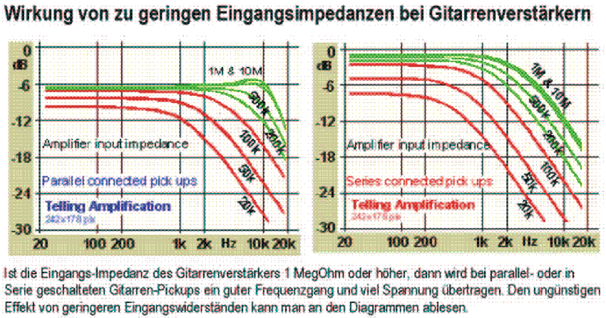
The Input Impedances of Guitar Amplifiers (RC pad)

| back |
Search Engine |
home |