
| Deutsche Version |
| To use the calculator, simply enter a value. The calculator works in both directions of the ↔ sign. |
 |
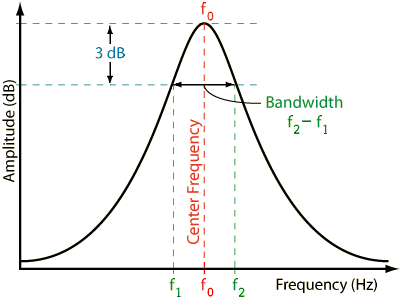
BW = Δf = f0 / Q Q = f0 / BW f0= BW × Q = √ (f1 × f2)
BW = f2 − f1 f1 = f02 / f2 = f2 − BW
f2 = f02 / f1 = f1 + BW
Conversion formula: 'octave bandwidth' N to quality factor Q:
 |
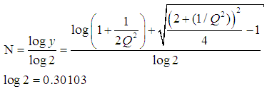
Conversion formula: Quality factor Q to 'octave bandwidth' N:
 |
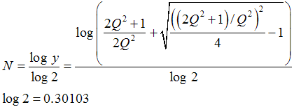
Also known is this longer formula with 4 Qs; see its development at:
Bandwidth in octaves versus Q in bandpass filters − RaneNote 170
 |
Frequency ratio of an octave:
 |
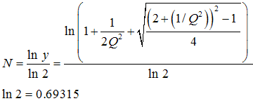
Formula to convert quality factor Q to 'bandwidth in octaves' N,
but with logarithmus naturalis:
 |
And the very short formula to convert quality factor Q
to 'bandwidth in octaves' N, but with sinh-1 :
 |
The conversion of the bandwidth in response to a different interval than the octave, such as the indication
of the "bandwidth as a function of a fifth" with the interval 2/3 or 1/2 octave is unusual.
|
Given −3 dB points to find bandwidth BW and quality factor Q. BW = f0 / Q Q = f0 / BW f0 =√ (f1 × f2) Given bandwidth in octaves N to find quality factor Q. Q = sqr(2^N) / (2^N − 1) Given quality factor Q to find bandwidth in octaves N. N = log(1 + 1 / (2 × Q2) + sqr(((2 + 1 / (Q2))2) / 4 − 1)) / log(2) |

Conversion chart or table
'bandwidth in octaves' N to quality factor Q
| BW in octaves |
Filter Q |
BW in octaves |
Filter Q |
BW in octaves |
Filter Q |
BW in octaves |
Filter Q |
|||
| 1/80 | 115.4 | 1 | 1.41 | 4 | 0.267 | 7 | 0.089 | |||
| 1/60 | 86.6 | 1 1/4 | 1.12 | 4 1/4 | 0.242 | 7 1/4 | 0.082 | |||
| 1/50 | 72.1 | 1 1/3 | 1.04 | 4 1/3 | 0.234 | 7 1/3 | 0.079 | |||
| 1/40 | 57.7 | 1 1/2 | 0.92 | 4 1/2 | 0.220 | 7 1/2 | 0.075 | |||
| 1/30 | 43.3 | 1 2/3 | 0.82 | 4 2/3 | 0.207 | 7 2/3 | 0.071 | |||
| 1/25 | 36.1 | 1 3/4 | 0.78 | 4 3/4 | 0.200 | 7 3/4 | 0.068 | |||
| 1/20 | 28.9 | 2 | 0.67 | 5 | 0.182 | 8 | 0.063 | |||
| 1/16 | 23.1 | 2 1/4 | 0.58 | 5 1/4 | 0.166 | 8 1/4 | 0.058 | |||
| 1/12 | 17.3 | 2 1/3 | 0.56 | 5 1/3 | 0.161 | 8 1/3 | 0.056 | |||
| 1/10 | 14.4 | 2 1/2 | 0.51 | 5 1/2 | 0.152 | 8 1/2 | 0.053 | |||
| 1/8 | 11.5 | 2 2/3 | 0.47 | 5 2/3 | 0.143 | 8 2/3 | 0.050 | |||
| 1/6 | 8.65 | 2 3/4 | 0.45 | 5 3/4 | 0.139 | 8 3/4 | 0.048 | |||
| 1/5 | 7.20 | 3 | 0.40 | 6 | 0.127 | 9 | 0.044 | |||
| 1/4 | 5.76 | 3 1/4 | 0.36 | 6 1/4 | 0.116 | 9 1/4 | 0.041 | |||
| 1/3 | 4.32 | 3 1/3 | 0.35 | 6 1/3 | 0.113 | 9 1/3 | 0.039 | |||
| 1/2 | 2.87 | 3 1/2 | 0.33 | 6 1/2 | 0.106 | 9 1/2 | 0.037 | |||
| 2/3 | 2.14 | 3 2/3 | 0.30 | 6 2/3 | 0.100 | 9 2/3 | 0.035 | |||
| 3/4 | 1.90 | 3 3/4 | 0.29 | 6 3/4 | 0.097 | 9 3/4 | 0.034 | |||
| 10 | 0.031 |
Q factor as a function of the bandwidth in octaves N
| Bandwidth in octaves N |
Filter Q factor |
| 3.0 wide | 0.404 low |
| 2.0 | 0.667 |
| 1.5 | 0.920 |
| 1.0 | 1.414 |
| 2/3 | 2.145 |
| 1/2 | 2.871 |
| 1/3 | 4.318 |
| 1/6 | 8.651 |
| 1/12 small | 17.310 high |
| Notice: A low Q factor gives a broad band (wide) bandwidth or a high Q factor gives a narrow band (small) bandwidth. |
| A high filter quality means narrow-band filtering (notch), with a large Q factor. This results in steep filter flanks with a small bandwidth. A low filter quality means broad-band filtering, with a small Q factor. This results in flat filter flanks with a large bandwidth. The larger the Q the more narrow is the resonance peak. The smaller the Q the more broad is the resonance peak. |
Notch filters have a large quality factor (Q), corresponding to a small bandwidth.
| The Q factor or the bandwidth does not tell the "steepness" in dB/oct. |
| Slope in dB/oct = steepness of the filter flanks ● Only with high pass and low pass filters − not with bell curves ● |
| Note: The Q factor (quality factor) or the bandwidth is not convertable to the "slope" as dB/oct. There are mastering equalizers with false information regarding the filter setting as "Slope in dB/octave" and not Q factor (width), see: Filter slope or steepness (dB/oct) is not bandwidth = Slope in dB/oct or steepness of filter slopes is not the bandwidth. |
| With "quality" is not meant how valuable the signal is. It is meant the quality of the filter. If the filter has flat slopes many frequencies are influenced around the cutoff frequency. The filter has therefore a larger bandwidth and the so-called quality factor Q is specified as a low number. If the filter has steep slopes, its bandwidth is smaller. Here a few frequencies below and above its cutoff frequency are affected and the quality factor Q is specified as a high number. |
| Why is the bandwidth and the cutoff frequency found at the level of "−3 dB"? Why we always take 3 dB down gain of a filter? Full width at half maximum (FWHM). Answer: That is the point where the energy (power) is fallen to the value ½ or 0.5 = 50 percent of the initial power as energy quantity, that is equivalent to (−)3 dB = 10×log(0.5). A (−)3 dB power drop is a decrease of 50 % to the value of 50 %. There the voltage is fallen to the value of √(½) or 0.7071 = 70.71 percent of the initial voltage as field quantity equivalent to (−)3 dB = 20×log(0.7071). A (−)3 dB voltage drop is a decrease of 29.29 % to the value of 70.71 %. |
| (−)3 dB implies ½ the electric power and since the power is proportional to the
square of voltage, the value will be 0.7071 or 70.71 % of the passband voltage. √½ = 1/√2 = √0.5 = 0,7071. P ~ V2, that is 0,5 ~ 0,70712. |
| Sound engineers and sound designers ("ear people") mostly use the usual (sound) field quantity. That's why they say: The cutoff frequency of a device (microphone, amplifier, loudspeaker) is the frequency at which the output voltage level is decreased to a value of (−)3 dB below the input voltage level (0 dB). ● (−)3 dB corresponds to a factor of √½ = 1/√2 = 0.7071, which is 70.71% of the input voltage. Acousticians and sound protectors ("noise fighters") seem to like more the (sound) energy quantity. They tell us: The cutoff frequency of a device (microphone, amplifier, loudspeaker) is the frequency at which the output power level is decreased to a value of (−)3 dB below the input power level (0 dB). ● (−)3 dB corresponds to a factor of ½ = 0.5, which is 50% of the input power (half the value). |
| Note: Power gain (power amplification) is not common in audio engineering. Even power amplifiers for loudspeakers don't amplify the power. They amplify the audio voltage that moves the voice coil. |
| Sound field quantities Sound pressure, sound or particle velocity, particle displacement or displacement amplitude, (voltage, current, electric resistance). Inverse Distance Law 1/r |
Sound energy quantities Sound intensity, sound energy density, sound energy, acoustic power. (electrical power). Inverse Square Law 1/r² |
| Note: A sound field quantity (sound pressure p, electric voltage V) is not a sound energy
quantity (sound intensity I, sound power Pak). I ~ p2 or P ~ V2. Sometimes you can hear
the statement: The cutoff frequency is there where the level L is decreased by (−)3 dB. Whatever the user wants to tell us so accurately: Level is level or dB is dB. |
| back |
Search Engine |
home |